Published 13 Jan 2020
Robotic Arm
Overview
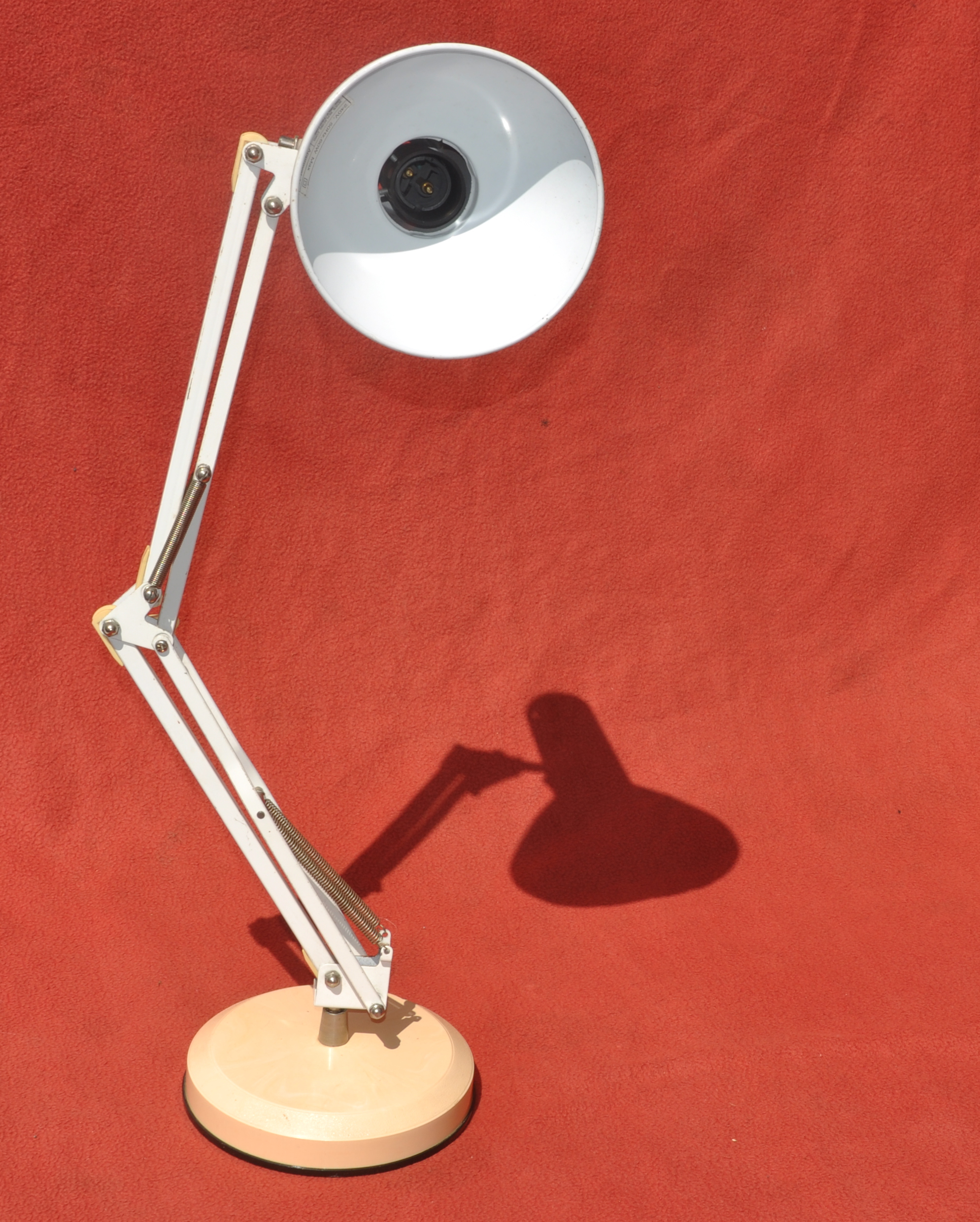
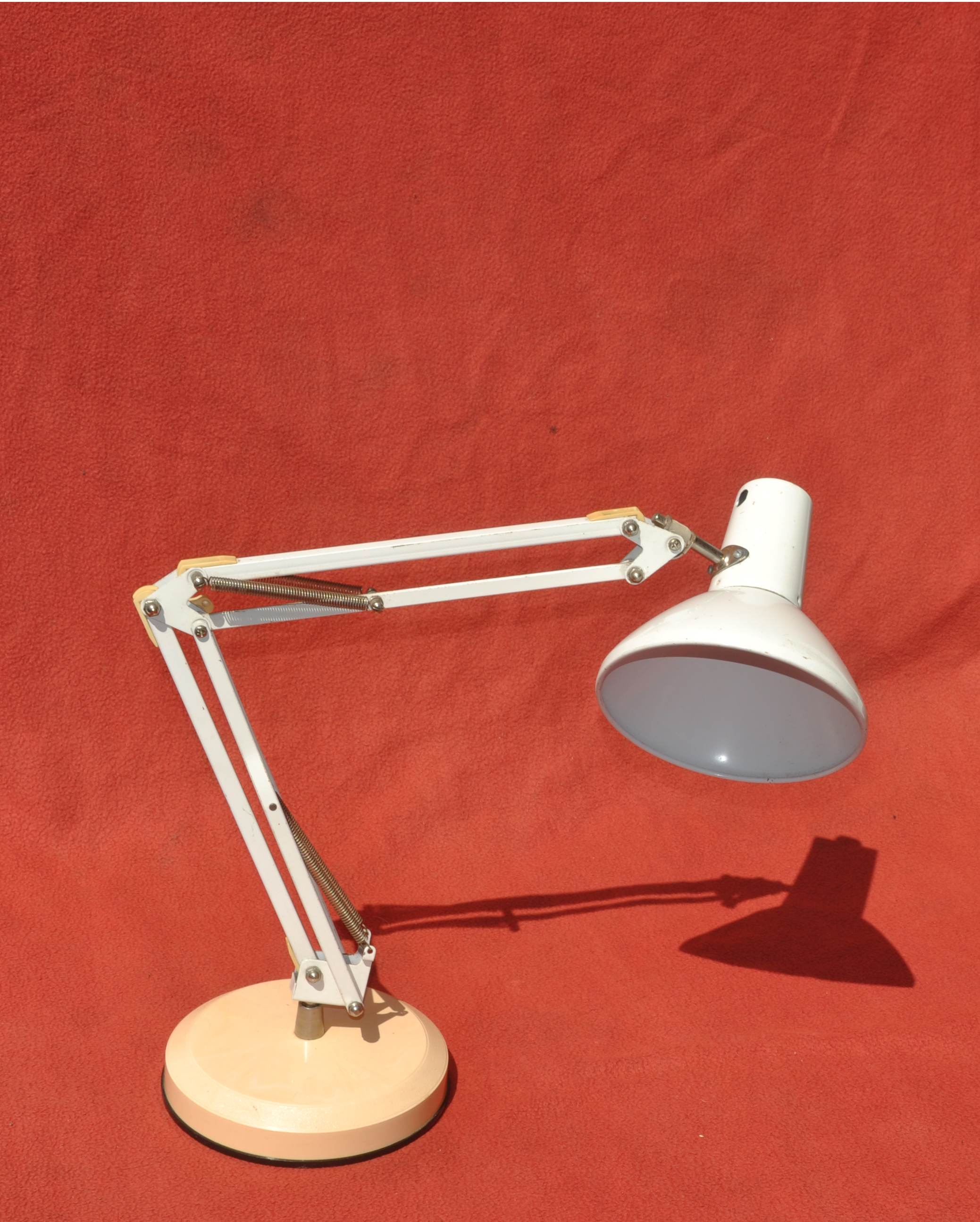
To build a computer controller robotic arm capable of moving with at least three degrees of freedom. It would seem attractive to re-use a mechanical assembly, like an extendable desk lamp arm, as the basis for this. My first attempt was using a Superlux Model C desklamp.
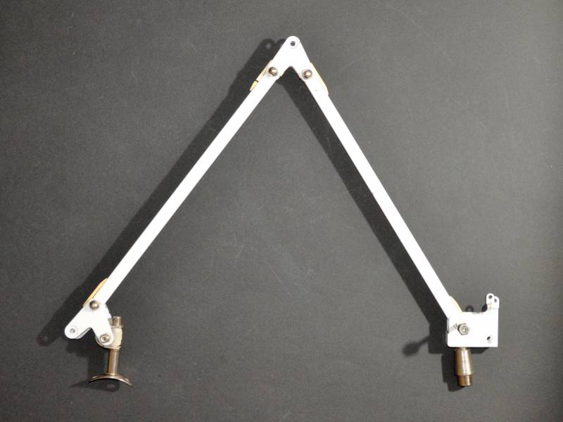
This example, Superlux Model C has quite short arms.
Hardware description
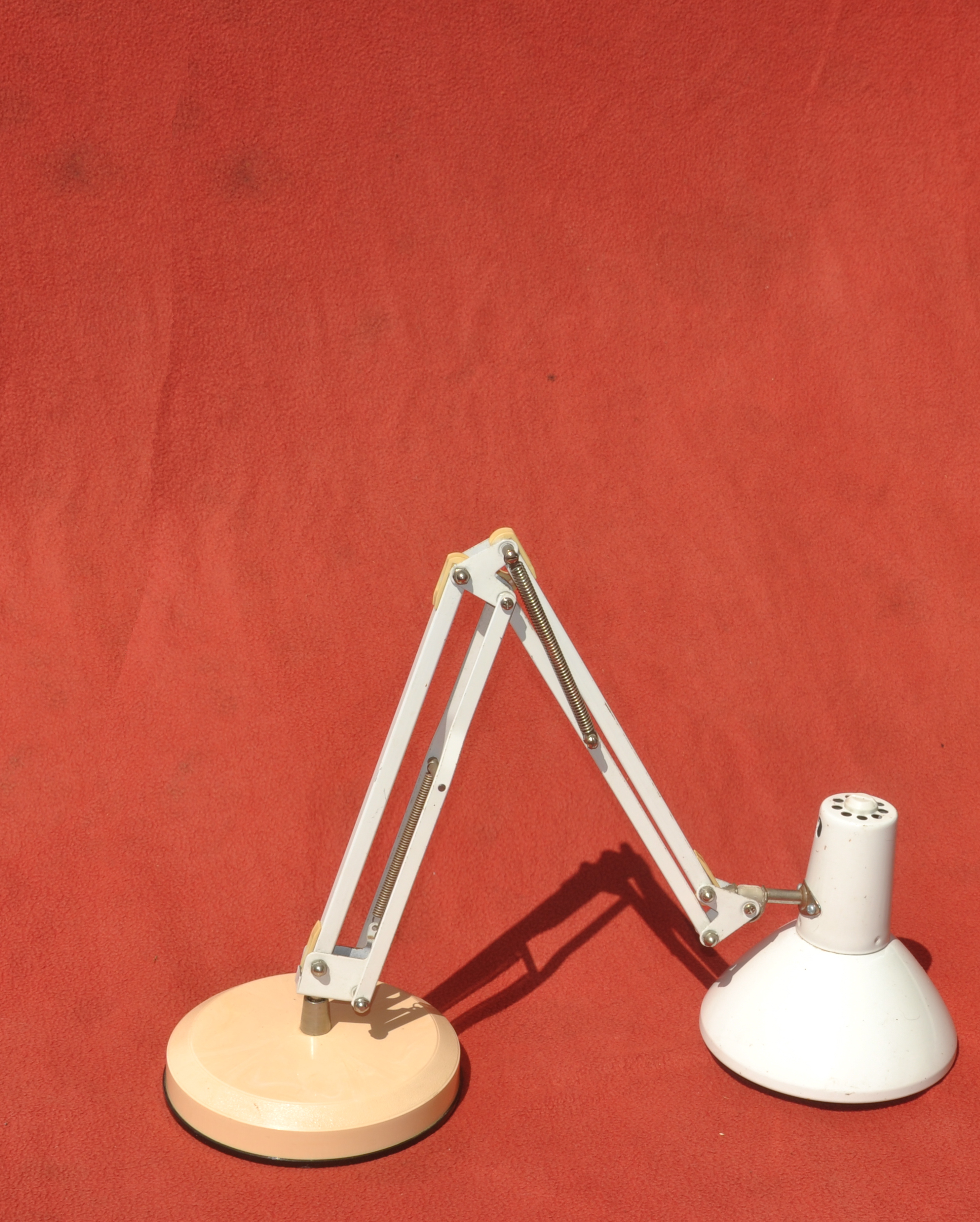
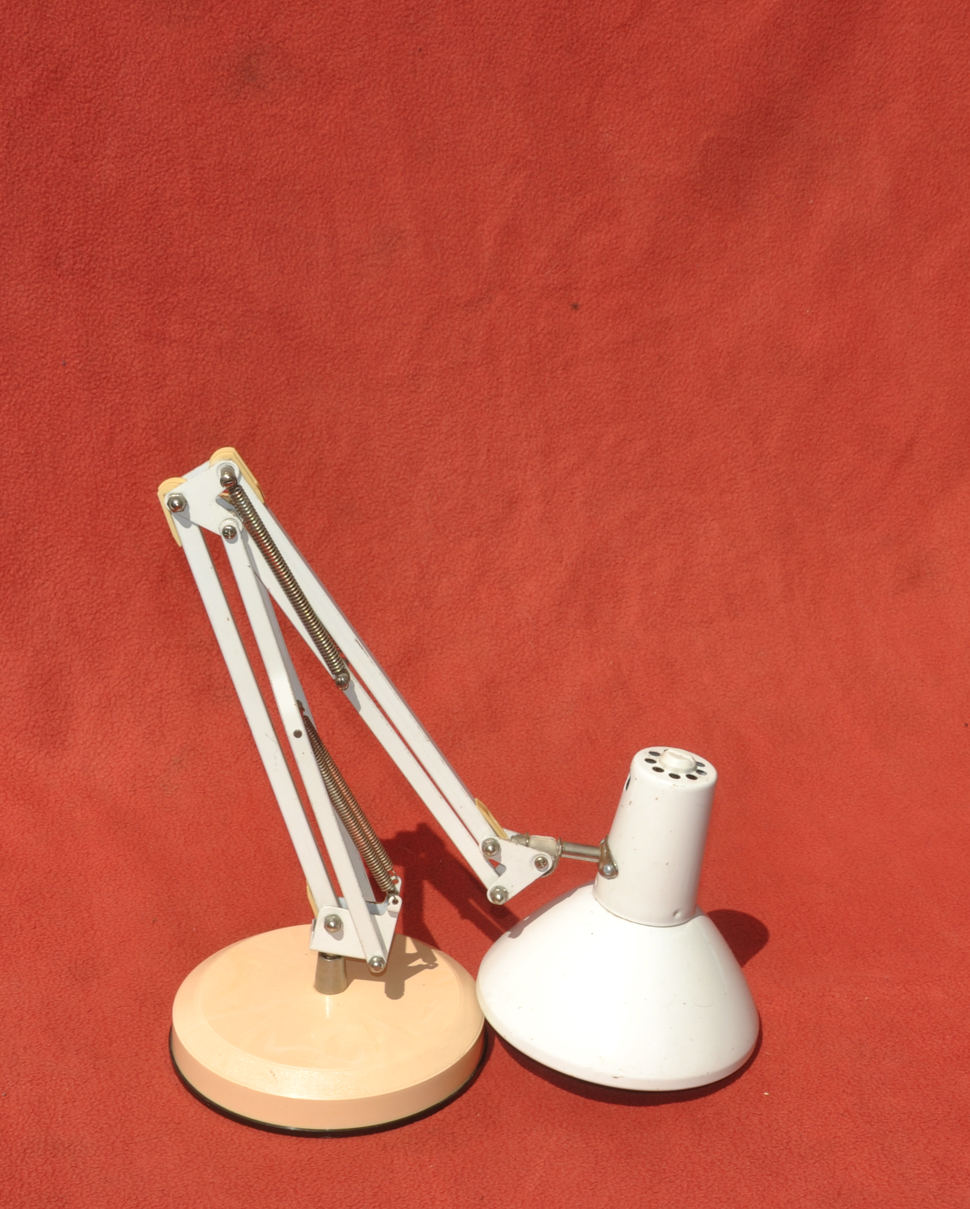
The arms are about 23cm long, the lower one constructed from three beams, the upper, 'fore', arm of only two beams. The lower beams forming each arm are on about 22.5cm centres, the upper beams seem slightly shorter, about 22.2cm between centres. The original payload of light fitting and bulb is about 256 grams (including bulb), this is partially counter-balanced by springs, so the arm will tend to maintain whatever position it is moved to. The springs would be unnecessary if using servos to drive the joints, as the servos would maintain position, in fact the springs would just add extra resistance to movement.
There are 5 joints that you would motorise - swivel at the base, up-down of the lower arm, up-down of the second arm, up-down of hand, swivel of the wrist. The base can swivel 360º (no stops), the lower arm can turn through about 150º, the upper arm can turn about 135º. The wrist can go up and down almost 180º and rotate about 285º.
On this particular arm design the 'hand' end of the arm can only reach the ground from a radius of about 33cm from the base out to 50cm with the arms fully extended horizontally. The under-beam of the fore-arm prevents it from bending enough to reach the ground at closer distances. Other lamps that have a square or pentagonal plate at the elbow, can bend without obstruction. Removing the under-beam of the forearm allows the 'hand' to reach the ground from the base out to 50cm, unobstructed.
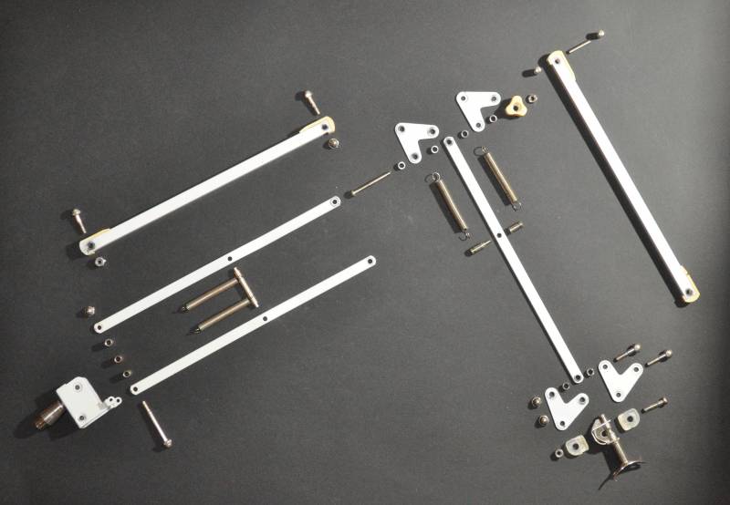
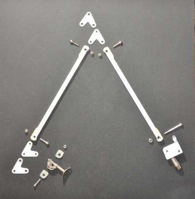
Exploded parts
Construction
After a bit of trial and error I selected components from the lamp arm to construct my robot arm. The springs and support struts didn't seem to be useful here and would just add weight.
Servos
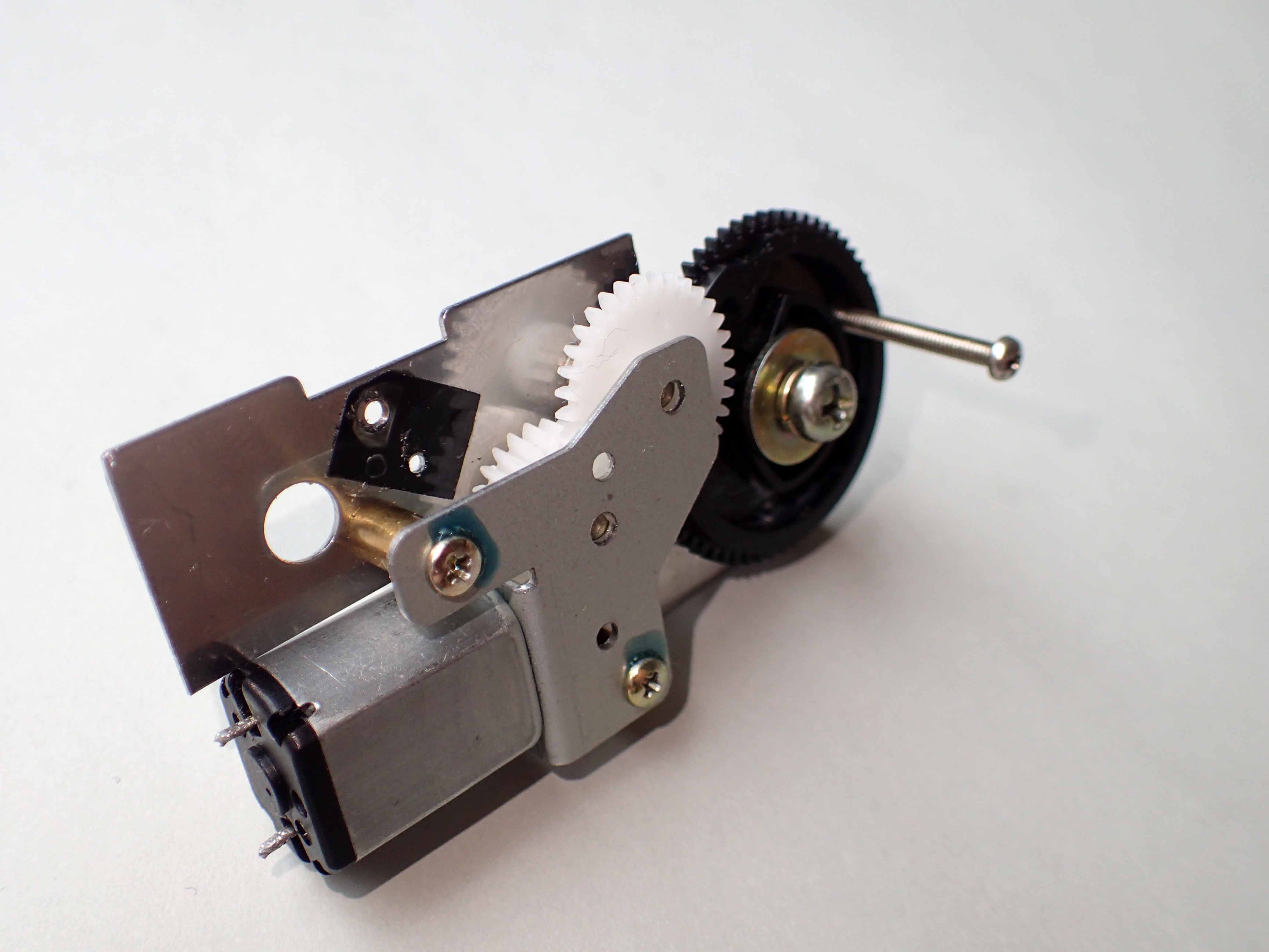
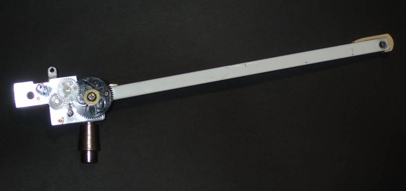
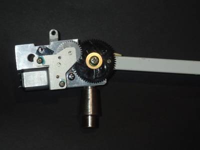
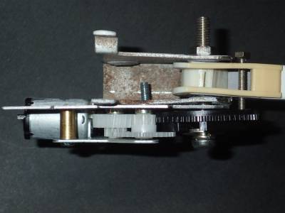
I didn't have a huge choice of actuators to use to articulate this arm, the first I tried is an old eject mechanism from a CD-ROM drive, XM-3301B eject mechanism
The servo was mounted so that the axle of the last servo gear, went through the pivot point of the arm. A drive pin was then inserted through the gear and further up the arm, so that as the gear turned, the arm was raised or lowered.
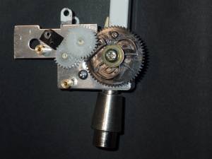
Servo mounted on base and attached to arm
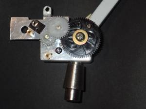
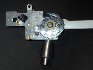
Movement of servo gear and robot arm
Assembled mechanism
Although the servo could raise and lower the arm, it didn't have enough power to lift anything else (not even the next segment of arm made from the desk-lamp). It could be used as a crane, the worm drive means it holds its position well, even without power on. The lifting would be done by a cable running over a pulley at the end of the boom, and powered by another motor with a spool, attached to the base. It still needs some form of positional feedback, for example a rotary potentiometer, shaft concentric with the axle, and body turned by the arm. Alternatively, limit switches to detect the top and bottom positions being reached - after calibration the duration that the servo motor is powered on could be used to estimate the arm position.

