Module data
Arduino
Arduino shields
Motor Controllers

| Module Description | |
|---|---|
| Model | USBCNC 2.1 |
| Manufacturer | Planet-CNC clone |
| Description | 4 Axis USB CNC interface |
| Other designations | CNCUSB MK1 USBCNC 2.1, A251A |
| Associated modules | |
| Voltage | 5V |
| Current | |
Overview
Designed to control a CNC machine, this board appears to be a later revision of the mk1 USB CNC controller from Planet-CNC.com. A number of manufacturers seem to have produced boards with an identical layout. I couldn't find this board anywhere on the archives of the Planet-CNC website (or old. Planet-CNC.com), but an image of it does occur in the archives of the forum. Planet-CNC.com and on xyzdiy.com :
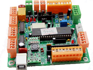

You can't quite read it in those photos, but on those PCBs just in front of the PIC chip it says http://www/planet-cnc.com which can be made out in other photos. But my example has 2012.06.07-10 http://xyzdiy.com on the underside and nothing on the topside. But I can't find mention of it on that website either. It is bigger and slightly more sophisticated than the Planet-CNC mk1 board, but uses the full size 40pin DIP PIC18F4550 chip, unlike the later Planet-CNC boards (mk2, mk3 etc).
Judging by the number of versions out there, I've got to suppose that there is a PDF, schematic etc floating around somewhere for it!
Hardware description
Components
- Microchip PIC18F4550-I/P (processor unit)
- 8 MHz crystal (CPU clock)
- LM331 voltage-to-frequency converter (spindle control)
- Two opto-isolators (spindle control)
- Two 74HC14 hex Schmitt trigger inverters (stepper signal buffers)
Regulated power supply module: Input 3-5.5V, output 5.1V 1A. I think earlier versions had problems caused by electrical noise from the stepper motors, so an onboard power regulator was added.
Features
- USB communication
- Standard RS274/NGC G-code support
- Four axes control (X,Y,Z,A)
- PWM inverter for spindle speed control
- Two outputs to control 5V relays
- One output from a switched relay
- Stepping rate maximum of 25 kHz
- Limit switch inputs for each axis
- Manual jog control (MPG) pendant support
- Onboard power regulator to avoid electrical interference

Uses a standard USB type B connector for communication from the computer sending the G-Code commands.
The buffered X,Y,Z,A outputs are for connecting to stepper motor drivers of the appropriate voltage and current rating for your motors.
There are three switched outputs (Out1, Out2 and Out3) for controlling mist, coolant, spindles etc. Out3 is a set of normally open (NO) relay contacts, and Out1/Out2 just have transistor buffers to drive something external. Each output has an associated activity LED.
A jumper is provided for selecting between providing (jumper left) Out1, or (jumper right) a PWM spindle speed control.
Two limit switch inputs for each axis are provided. Each switch connects that input to ground (they can be normally open (NO), or normally closed (NC) switches depending on the firmware settings)
A set of jogging key inputs and a manual speed control (50k log pot) connection are provided so that the CNC device can be operated manually via a pendant control.
Revisions
This board appear to have been a redesign of the published Planet-CNC.COM mk1 board to address issues like a of lack of electrical noise suppression (eg lack of bypass capacitors) and to add a few enhancements. The board appears to have been designed with provision for IDC ribbon cable connectors or screw terminals, but I've only seen the screw terminal versions advertised, and my one didn't even come with the IDC socket for the jog pendant, that I've seen on other copies of this board.
Examples


References and Additional Resources
Page Tools
 Except where otherwise noted, content on this wiki is licensed under the following license: CC Attribution-Share Alike 3.0 Unported