Published 18 Aug 2022
Ks0073 Driver Library
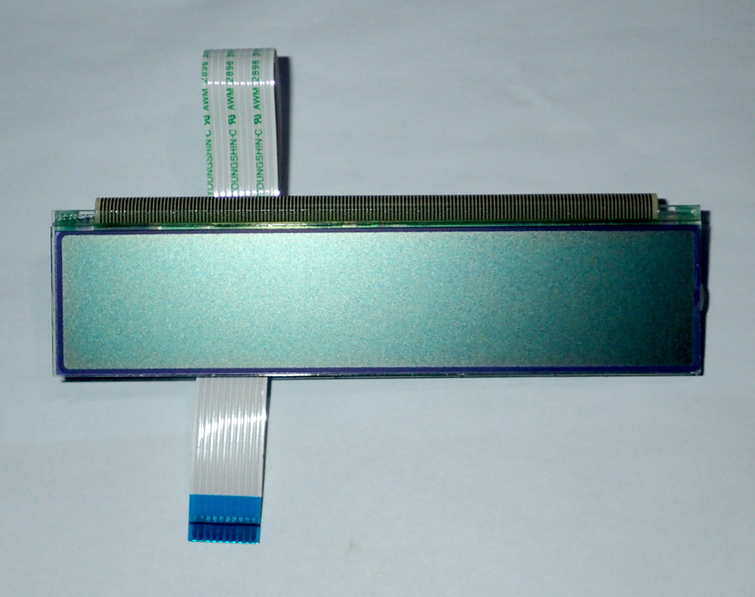
I have a pile of display panels from Siemens optiPoint 500 series phones, that I wish to use in Arduino projects. These are 2 line by 24 character LCD status displays, controlled by Samsung KS0073 - a Hitachi HD44780 compatible LCD controller/driver chip that includes an SPI style serial interface.
Overview
I looked for an Arduino library that would talk to this chip-set, but failed to find one.
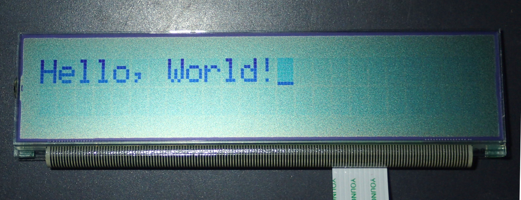
I based my library module for this on a standard Arduino library for the Hitachi HD44780 chip, LiquidCrystal.cpp. The programs included here are HelloWorld.ino, LiquidCrystal_ks0073.cpp and LiquidCrystal_ks0073.h.
The command set is compatible with the Hitachi HD44780 with extensions.
Hardware description
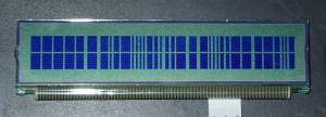 The KS0073 controller chip is capable of 4 or 8 bit parallel and SPI style serial interfacing, but in these modules it is hardwired for serial only. The controller is mounted on a PCB and joined to the LCD glass via a PCB flex cable. I think the flex cable is a weak point in the design as some modules display missing columns of pixels (best observed when the contrast is turned right up where upon some characters only show as narrow strips rather than solid blocks - pressure on the cable changes which columns of pixels are displayed).
The LCD module has a 10 pin, 1mm pitch, PCB flex cable to connect to a suitable socket.
The displays are a two lines of twentyfour, 5 by 8 pixel, characters.
 .
.
The ks0073 controller chip has two sets of, very similar, instructions available. They are selectable via the Extended Instruction control pin (IE). In the VLGEM1021 modules this appears to be tied “low”. I assume that this pin is to allow the chip to emulate either of two previous LCD control chip implementations.
Arduino to VLG1021 LCD wiring
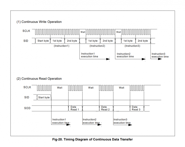
The great advantage of these serial SPI LCD modules is the simplicity of the Arduino interface. There are four signal lines SID (data to the display), SOD (responses from the display), SCLK (clock), and CS (select). Plus power (+5V) and ground (the module should also work from a 3.3V supply). CS is really only needed if there is more than one display connected to SCLK, SID and SOD, so it could be tied to ground to permanently enable the interface. SOD is mainly used for checking the ready state of the LCD module after each command, if speed isn't crucial then just implementing a wait after each command (about 40uS usually), means you can get away with just using SCLK and SID - so requiring only two Arduino pins for full control of the device.
There is a separate power line, VCI, to supply the voltage converter that sets the LCD contrast voltage, around 1.3V was typical.
The interface pins can be any available Arduino pins.
KS0073 LCD Library
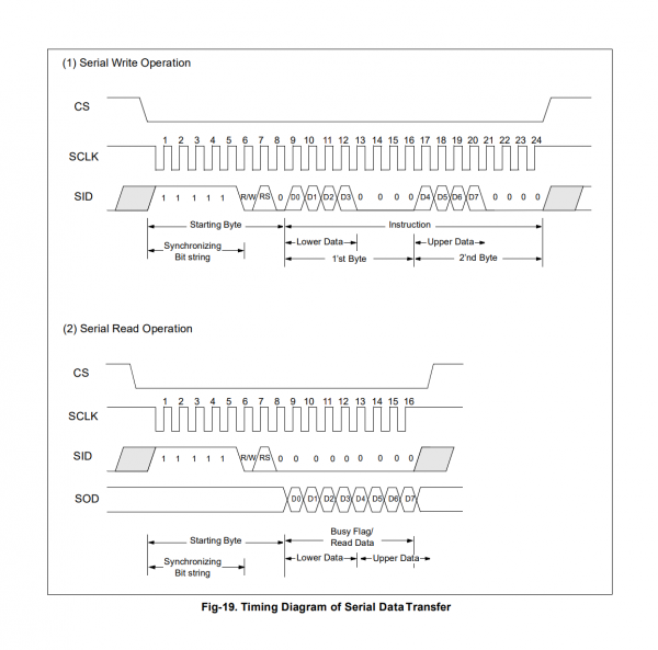
The KS0073 uses its own variation of a SPI protocol where data and commands are prefixed by a control byte that specifies what the following bytes are going to be - ie read/write data, or a command.
All bytes are sent least significant bit (LSB) first, on the rising edge of SCLK. The control byte consists of 5 successive “1”s followed by read/write (R/W) and command/data register select (RS) bits. The final bit of the control byte is a “0”, making a total start sequence of 8 bits. So typically you assert CS and send a control byte indicating a command follows, then the command. If there is data to be sent, send a control byte followed by a stream of data bytes terminated by releasing SS. Both commands and data are split into two nibbles and a prefix of four “0”s is added to each - so there will never be a stream of commands or data containing five successive “1”s. ie to send 00011111, you send 0000 0001 0000 1111. So the KS0073 can always unambiguously re-synchronise to the command stream.
I used a minimum of 2uS for the clock cycle for SCLK and, as I was not checking the ready status of the chip, a delay of about 40uS between sending bytes to give sufficient time for the chip's internal processing.
As mentioned earlier the library is based on a standard Arduino HD44780 LCD library. Most hardware commands, including programmable characters, seem to be compatible with the HD44780. There are a number of chip features that are not supported by this driver, such as “Low power mode”, “Dot scrolling” (shifting the display window by 1 dot increments), “Bidirectional segment addressing” (horizontal mirroring of display), “4-line mode” (for 4 line displays), “Inverting cursor” and “6-dot font width”. This is mainly because I couldn't test them with the VLGEM1021 LCM.
The functions implemented are:
- begin(col,row)
- Initializes the display, usually done once in a sketch's setup() routine.
- clear()
- Clears the screen of all pixels and homes the cursor.
- home()
- Sets the location for next data output (cursor location) to 0,0.
- display();
- noDisplay();
- Turns the display on or off.
- blink();
- noBlink();
- Turns the blinking cursor on or off.
- reverse()
- noReverse()
- Turns on or off reverse video mode (white on black, rather than black on white characters)
- (only works when the ks0073 chip has Extended Instruction (IE) pin tied “high”)
- setCursor(col, row)
- Set location for next character to be displayed.
- cursor()
- Show cursor at location ready for next character.
- noCursor()
- Turn off cursor display.
- scrollDisplayLeft()
- Scroll current line one character to the left.
- scrollDisplayRight()
- Scroll current line one character to the right.
- leftToRight()
- Normal Western language display mode where words are written starting at the left of the display.
- rightToLeft()
- Mode used for Japanese and other languages where characters are written starting at the right of the display.
- autoScroll()
- Automatically scroll when the cursor (whether visible or not) reaches the far edge of the display.
- noAutoscroll()
- Turns off autoscroll.
- createChar()
- Programs one of the 8 user defined, 5×8 pixel characters.
The functions appear to be the same as for the HD44780 but have not been extensively tested for compatibility.
After setting a programmable character future writes also go to the programmable character CGRAM (corrupting it) until you deliberately switch back to the display ram. This is a problem from the original LiquidCrystal.h library - the solution here is that I just reset the cursor to the home location after programming characters.
The programs (v1.01):
- helloworld.ino, sketch to test the LCD library
- liquidcrystal_ks0073.h, KS0073 SPI LCD library
- liquidcrystal_ks0073.cpp, KS0073 SPI LCD library
References and Additional Resources
- KS0073 dot matrix LCD driver & controller.
Other Arduino LCD drivers
- METP0000, NEC µPD7225 based LCD display panel Arduino driver
- Canon MX300, Canon MX300/310 printer LCD display panel Arduino driver.
- NEC µPD7228 and μPD16434 LCD display panels Arduino driver
- SPI LCD, LCD display panel Arduino driver
- Toshiba T6A34 SPI, HD44780 compatible, LCD display panel Arduino driver
If any referenced page no longer exists, try looking for its URL on http://archive.org.
